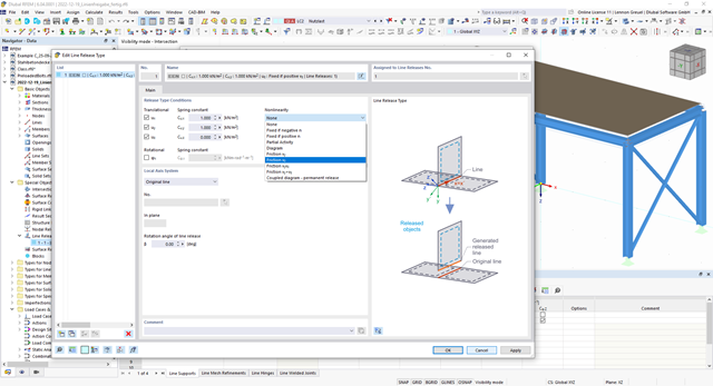
You can simulate the static friction effects between two supporting components along a line using the "Friction" nonlinearity in the Line Release Type.
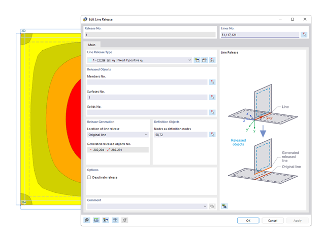
You probably already know that node, line, and surface releases are used to define transfer conditions between objects. For example, you can release members, surfaces, and solids from a line. It is also easily possible for the releases to have nonlinear properties, such as "Fixed if positive n", "Fixed if negative n", and so on.

Have you created the entire structure in RFEM? Very well, now you can assign the individual structural components and load cases to the corresponding construction stages. In each construction stage, you can modify release definitions of members and supports, for example.
You can thus model structural modifications, such as those that occur when bridge girders are successively grouted or when columns are settled. Then, assign the load cases created in RFEM to the construction stages as permanent or non-permanent loads.
Did you know that The combinatorics allows you to superimpose the permanent and non-permanent loads in load combinations. In this way, it is possible for you to determine the maximum internal forces of different crane positions or to consider temporary mounting loads available in one construction stage only.
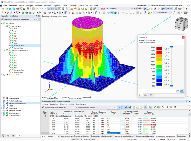
If you release a structural component with a nonlinear elastic material again, the strain goes back on the same path. In contrast to the Isotropic|Plastic material model, there is no strain left when completely unloaded.
You can select three different definition types:
- Standard (definition of the equivalent stress under which the material plastifies)
- Bilinear (definition of the equivalent stress and strain hardening modulus)
- Stress-Strain Diagram:
- Definition of polygonal stress-strain diagram
- Option to save / import the diagram
- Interface with MS Excel
Background information about nonlinear material models can be found in the technical article describing the yield laws in isotropic nonlinear elastic material model.
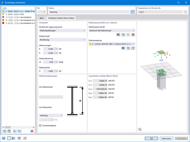
If you are working with nonlinearities, this feature is suited very well to support you. For example, you can specify nonlinearities of member end releases (yielding, tearing, slippage, and so on) and supports (including friction). Furthermore, you can use special dialog boxes to determine the spring stiffnesses of columns and walls based on the geometry specifications.
RFEM offers the following tables to display forces and deformations of hinges and releases:
- 4.45 Line Hinges - Deformations
- 4.46 Line Hinges - Forces
- 4.47 Member Hinges - Deformations
- 4.48 Member Hinges - Forces
- 4.49 Nodal Releases - Deformations
- 4.50 Nodal Releases - Forces
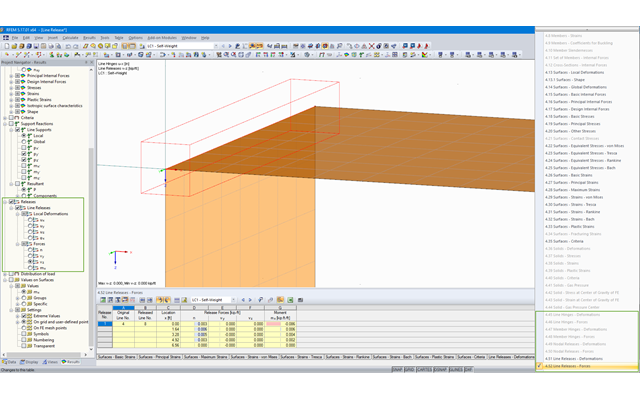
- 4.51 Line Releases - Deformations
- 4.52 Line Releases - Forces
The tables can be displayed in the prinout report. Moreover, the results in line hinges and line releases can be displayed graphically. It can be controlled by Project Navigator - Results.

- Nonlinear member types, such as tension and compression members or cables
- Member nonlinearities, such as failure, tearing, yielding under tension or compression
- Support nonlinearities, such as failure, friction, diagram, and partial activity
- Release nonlinearities, such as friction, partial activity, diagram, and fixed if positive or negative internal forces
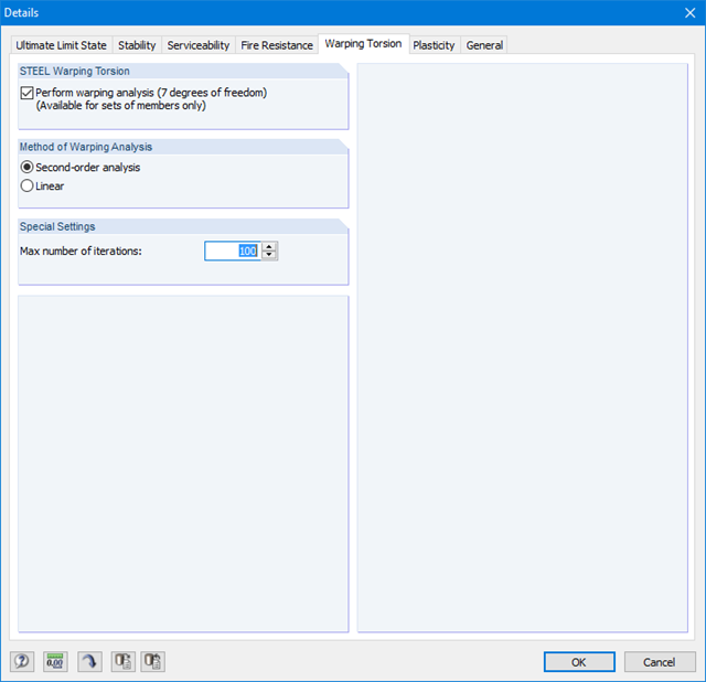
Since RF-/STEEL Warping Torsion is fully integrated in RF-/STEEL AISC and RF‑/STEEL EC3, the data are entered in the same way as for the usual design in these modules. It is only necessary to select the option "Perform warping analysis" in the Details dialog box, tab Warping Torsion (see the figure on the right). You can also define the maximum number of iterations in this dialog box.
The warping torsion analysis is performed for sets of members in RF-/STEEL AISC and RF‑/STEEL EC3. You can define boundary conditions such as nodal supports or member end releases for them.
It is also possible to specify imperfections for the nonlinear calculation.
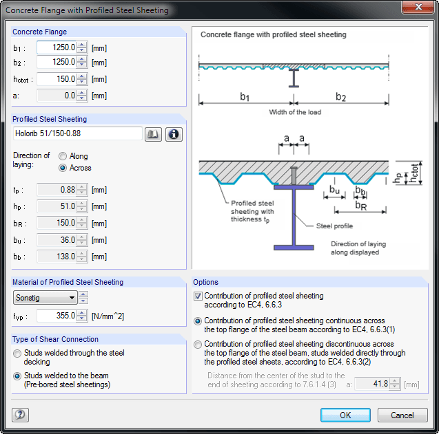
When entering the structural model, you can define single-span and continuous beams with or without cantilevers. Furthermore, it is possible to specify different span lengths with definable boundary conditions (supports, releases) as well as any construction support and moment release in the construction stage. For a complete cross-section, you can create typical composite beam sections on the basis of steel girders (I-sections) with solid concrete flanges, precast plates, trapezoidal sheets, or tapered solid ceilings.
It is also possible to grade cross-sections by means of beam lengths, optionally with concrete encasement. Illustrative figures facilitate the entry of additional transverse reinforcements for trapezoidal sheeting, profile stiffeners, and angled or circular openings in the web. The self-weight is applied automatically when entering loads. In addition, it is possible to consider fixed and variable loads by specifying the concrete age at the beginning of loading for creeping, and to define single, uniform, and trapezoidal loads freely. COMPOSITE-BEAM automatically creates a load combination based on the data of individual load cases.
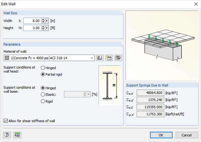
It is possible to specify nonlinearities of member end releases (yielding, tearing, slippage, and so on) and supports (including friction). There are special dialog boxes available for determining the spring stiffnesses of columns and walls based on the geometry specifications.
.png?mw=640&hash=53c64389797699e939283ddbfc3d88485fcbfbf5)
- Full integration in RFEM/RSTAB, including import of all relevant loads
- General stress analysis with warping torsion according to elastic-elastic method
- Stability analysis of planar continuous members for buckling and lateral-torsional buckling
- Determination of critical load factor and thus of Mcr or Ncr (the factor can be used in RF-/LTB for the el/pl design)
- Lateral-torsional buckling analysis of any cross-section (also the SHAPE-THIN cross-sections)
- Design of members and sets of members with applied torsion (for example, crane girder)
- Optional determination of the limit load factor (critical load factor)
- Display of eigenmodes and torsional modes on the rendered cross-section
- Wide range of tools for determining shear panels and rotational restraints (such as corrugated sheets, purlins, bracings)
- Easy determination of discrete springs such as warp springs from end plates or rotational springs from columns
- Graphical selection of load application points on a cross-section (upper chord, centroid, lower chord, or any other point)
- Free arrangement of eccentric nodal and line supports on a cross-section
- Determination of value for inclination or precamber by means of eigenvalue analysis
- Special warping releases applicable for definition of warping conditions on transitions
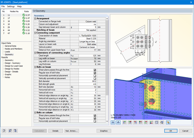
All joint types are considered with the moment release at the column flange, or at the column web in the case of a rotated column. Therefore, the module determines the eccentric moment of a web cleat and fin plate connection, which additionally affects the bolt group at the girder flange.
Further eccentric moments may result from the locations of the angles and sheets. In the case of cleat connection, the forces are transferred separately. Shear forces act on the cleat; tension forces and stabilizing moment are assigned to the bolts. Before the calculation, the connection is checked for geometrical plausibility; for example, the bolt hole spacing and edge distance of the bolts.
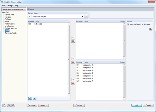
After creating the entire structure in RFEM/RSTAB, the individual structural components as well as load cases and combinations are assigned to the corresponding construction stages. For each construction stage, you can modify for example release definitions of members and supports.
Thus, it is possible to model structural modifications, such as those that occur when bridge girders are successively grouted or when columns are settled. The load cases and load combinations already created in RFEM/RSTAB are divided into "Permanent Loading" and "Temporary Loading" in the add-on module.
The defined temporary loads are superimposed by permanent loads. This way, it is possible to determine the maximum internal forces of different crane positions or to consider temporary mounting loads available only in one construction stage.